| m11 | m12 | m13 |
| m21 | m22 | m23 |
| m31 | m32 | m33 |
And the position (in world space) [px, py, pz]
Give the rotation matrix (in world space) and the position (in world space) of Spaceship 2
SolutionSpaceship 2 should share the same up vector as Spaceship 1, but be pointed in the opposite direction. Thus, we just need to invert the x and z axes to get the position:
| -m11 | -m12 | -m13 |
| m21 | m22 | m23 |
| -m31 | -m32 | -m33 |
Note that if we had just inverted the z axis (and not changed the X axis), then we would have not only turned the ship around, but also mirrored it.
The position of ship 2 is just the position of ship 1 plus the distance times the facing vector of ship 1:
[px, py, pz] + 20 [m31, m32, m33]| m11 | m12 | m13 |
| m21 | m22 | m23 |
| m31 | m32 | m33 |
And the position (in world space) [px, py, pz]
You wish to place a camera 10 units directly to the right of the character, pointing at the character (that is, looking at the character's right shoulder), with the same up vector as the character.
Give the rotation matrix (in world space) and the position (in world space) of the camera.
SolutionThe up vector of the camera is the same as the up vector of the character, so the first part of the rotation matrix is easy enough:
| m21 | m22 | m23 |
Next, consider the facing vector of the camera. The camera is pointing at the right shoulder -- in the same direction as the left vector of the character.
| m21 | m22 | m23 |
| m11 | m12 | m13 |
At this point, we could use a cross product to get the left vector (up cross facing == left), or we could note that the left vector of the camera is pointing in the opposite direction of the facing vector of the character:
| -m31 | -m32 | -m33 |
| m21 | m22 | m23 |
| m11 | m12 | m13 |
Now, for the position of the camera -- it is just the position of the character + the scalar distance * -(left vector)
[px, py, pz] - 10 [m11, m12, m13]
| m11 | m12 | m13 |
| m21 | m22 | m23 |
| m31 | m32 | m33 |
And the position (in world space) [px, py, pz]
The ground is perpendicular to the world up vector. You wish to place a camera 10 units away from the character, along the line you get when you project the x axis to the ground plane. The camera should have the same up vector as as the world, and be pointed at the character. (See diagram) You can assume that [m11, m12, m13] != [0, 1, 0] and [m11, m12, m13] != [0, -1, 0] (so that x has a non-zero projection to the ground plane).
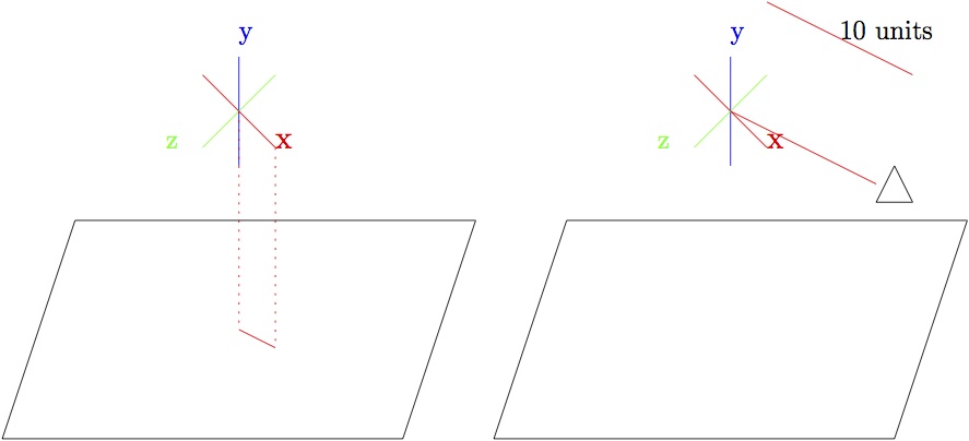
First off, the x vector of the object is: vx = [m11, m12, m13]. If we project this onto the ground plane, we get [m11, 0, m13]. Normalizing this vector gives us [m11/d, 0, m13/d], where d = sqrt(m112 + m132). If we add 10 * this normalized vector to the original point, we get the position of the camera:
Camera position = [px, py, pz] + 10 * [m11/d, 0, m13/d], where d = sqrt(m112 + m132)
Now, let's look at the orientation of the camera. The up vector of the camera is the same as the up vector of the world: [0, 1, 0]. The z vector of the camera is the opposite of the projected X vector: [-m11/d, 0, -m13/d]. So we have
| 0 | 1 | 0 |
| -m11/d | 0 | -m13/d |
What about the x vector of the camera? Well, we have the y and z vectors, and the cross product y × z = x, so x = [0, 1, 0] × [-m11/d, 0, -m13/d] = [-m13/d, 0, m11/d]. So, we finally have:
| -m13/d | 0 | m11/d |
| 0 | 1 | 0 |
| -m11/d | 0 | -m13/d |
| m11 | m12 | m13 |
| m21 | m22 | m23 |
| m31 | m32 | m33 |
after applying a transform M, we are left with:
| -m11 | -m12 | -m13 |
| -m31 | -m32 | -m33 |
| m21 | m22 | m23 |
Does the transformation M contain a reflection?
SolutionThe transformation inverts an axis (reflection) then inverts another axis (undoing reflection) then inverts a third axis (reflection) then swaps two axes (undoing the reflection). No reflection.
- [w, (x, y, z)] and [-w, (x, y, z)]
OK, so this one problably should have been 3rd instead of 1st, Go look at the solutions to the next two problems, and the come back. So, if we negate the vector value, that results in rotating -Θ degrees around the same axis. If we then negate the entire quaternion, we are left with the same displacement (rotating -Θ degrees around the original axis). So, the second quaternion rotates around the same axis as the first quaternion, by the same amount, but in the opposite direction.
- [w, (x, y, z)] and [w, (-x, -y, -z)]
- [w, (x, y, z)] and [-w, (-x, -y, -z)]
- [w, (x, y, z)] and [w, (-x, y, z)]
- [w, (x, y, z)] and [w, (x, -y, z)]
- [w, (x, y, z)] and [w, (x, y, -z)]
- [w, (x, y, z)] and [w, (-x, -y, z)]
We can get from quaternion 1 to quaternion 2 by leaving the angle Θ the same, and inverting the x and y coordinates of the axis we are rotating around. So, if quaternion 1 repersents rotation by Θ degres around a vector n, quaternion 2 represents rotating by Θ degrees around the vector n', which is just n reflected first about the yz-plane, then around the zx-plane
So we have negated the vector portion of the quatenrion,
while leaving the real portion alone. So we are rotating by the
same angle, but the vector representing the rotation axis has
flipped. Thus if the first quaternion represents a rotation
of Θ
degrees around the axis n, then the second quaternion represents a
rotation of -Θ degrees around the same axis n
Recall that negating a quaternion does not change the orientation represented by the quaternion -- so these two quaternions represent the same angular displacement. Looking at it another way, we are both inverting the axis (which would be the same axis in the opposite direction) and also inverting the direction of rotation, leaving the same displacement
We can get from quaternion 1 to quaternion 2 by leaving the angle
Θ the same, and inverting the x coordinate of the axis we are
rotating around. So, if quaternion 1 repersents rotation by
Θ degres around a vector n,
quaternion 2 represents rotating by Θ degrees around the
vector n',
which is just n
reflected about the yz-plane.
We can get from quaternion 1 to quaternion 2 by leaving the angle Θ the same, and inverting the y coordinate of the axis we are rotating around. So, if quaternion 1 repersents rotation by Θ degres around a vector n, quaternion 2 represents rotating by Θ degrees around the vector n', which is just n reflected about the zx-plane.
We can get from quaternion 1 to quaternion 2 by leaving the angle
Θ the
same, and inverting the z coordinate of the axis we are rotating
around. So, if quaternion 1 repersents rotation by
Θ degres around a
vector n,
quaternion 2 represents rotating by Θ degrees around the
vector n',
which is just n
reflected about the xy-plane.
- [1, (0, 0, 0)]
- [0, (0, 1, 0)]
- [1/sqrt(2), (1/2, 1/2, 0)]
cos (Θ/2) = 1/sqrt(2) ==> Θ/2 = 45 degrees (or π/4 radians), so Θ = 90 degrees (or π/2 radians). Both the x and z components of n have the same positive value (with the z component == 0), so n (normalized) must be the vector [1/sqrt(2), 1/sqrt(2), 0]. (Alternate method for calculating n: Θ/2 = 45 degrees, so sin(Θ/2) = 1/sqrt(2) So, 1/sqrt(2) * n = [1/2, 1/2, 0], so n = [1/sqrt(2), 1/sqrt(2), 0].
This is the identity quaternion -- represents rotating 360 degrees around (any) axis, which is equivalent to no rotation at all.
cos (Θ/2) = 0 ==> Θ/2 = 90 degrees (or π/2 radians), so Θ = 180 degrees (or π radians). Since the x and z components of n are both 0, this is then a rotation of 180 degrees (or π radians) around the y axis.
Ogre::Vector3 shipPos;
Ogre::Quaternion shipOrientation;
The spaceship has an orbiting satelite whose position and orientation (relative to the spaceship) are:
Ogre::Vector3 satelitePosLocal;
Ogre::Quaternion sateliteOrientationLocal;
- Give code to calculate the position and orientation of the satelite in world space:
Ogre::Vector3 satelitePosGlobal = ...
Ogre::Quaternion sateliteOrientationGlobal = ...
Solution
Ogre::Vector3 satelitePosGlobal = shipOrentation * satelitePosLocal + shipPos;
Ogre::Quaternion sateliteOrientationGlobal = shipOrientation * sateliteOrentation;
- You have a point in satelite space:
Ogre::Vector3 pointInSateliteSpace;
Give code to transform that point into world space:Ogre::Vector3 pointInWorldSpace =
SolutionOgre::Vector3 pointInWorldSpace = shipPosition + shipOrentation * (sateliteOrientationLocal * pointInSateliteSpace + satelitePos) - You have a point in world space:
Ogre::Vector3 pointInWorldSpace;
Give code to transform that point into satelite space:Ogre::Vector3 pointInSateliteSpace = ...
SolutonOgre::Vector3 pointInSateliteSpace = sateliteOrientation.inverse() * (shipOrentation.inverse() * (pointInWordSpace - shipPosition) - satelitePos)
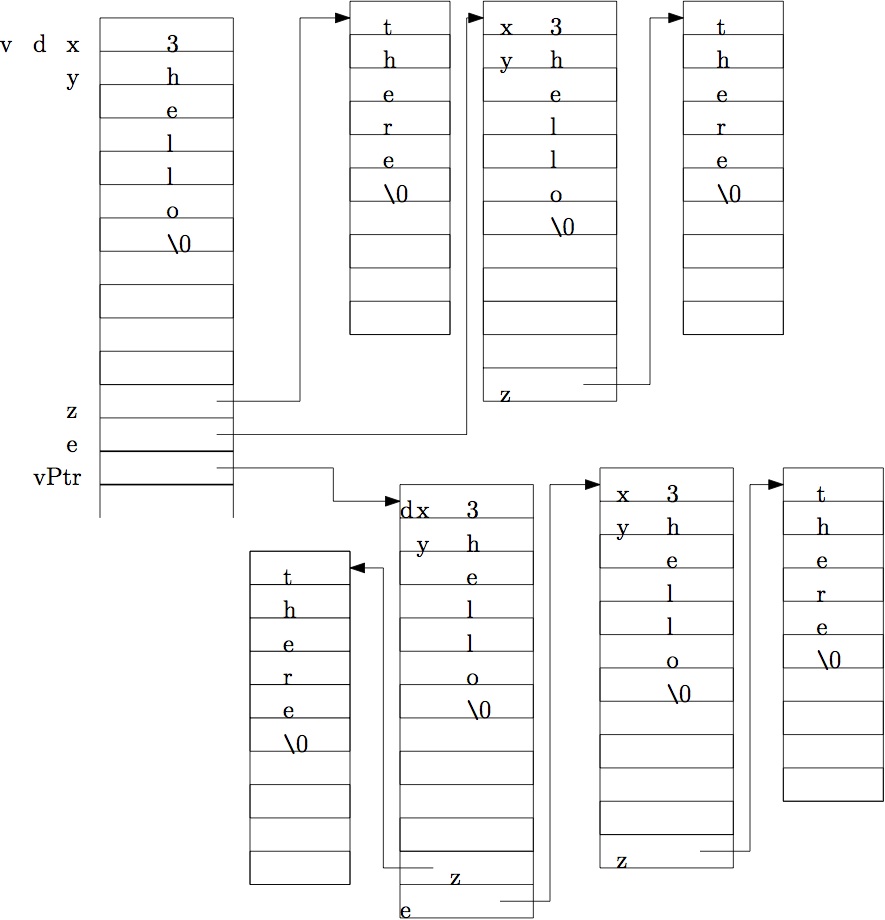
class foo
{
    foo(int a, char *b, char *c) : x(a) {
       strcpy(y,b);
       z = new char[strlen(c) + 1];
       strcpy(z,c);
    }
    int x;
    char y[10];
    char *z;
};
class bar
{
   bar(int g, char * h, char *i) : d(g, h, i)
   {
      e = new foo(g, h, i);
   }
   foo d;
   foo *e;
};


int main()
{
   bar v(3, "hello", "there");
   bar *vPtr = new bar(5, "test", "string");
  // Point A
}
Show the contents of the stack and heap at Point A
#includeSolutionclass A { public: void P1() {printf("P1 in A\n");} virtual void P2() {printf("P2 in A\n");} virtual void P3() {printf("P3 in A\n");} }; class B : public A { public: void P1() {printf("P1 in B\n");} void P2() {printf("P2 in B\n");} }; class C : public B { public: void P1() {printf("P1 in C\n");} void P2() {printf("P2 in C\n");} void P3() {printf("P3 in C\n");} }; int main() { A aVar; B bVar; C cVar; A *aPtr = new C(); B *bPtr = new C(); aVar.P1(); aVar.P2(); aVar.P3(); printf("--------\n"); bVar.P1(); bVar.P2(); bVar.P3(); cVar.P1(); cVar.P2(); cVar.P3(); printf("--------\n"); aPtr->P1(); aPtr->P2(); aPtr->P3(); bPtr->P1(); bPtr->P2(); bPtr->P3(); printf("--------\n"); aVar = cVar; aVar.P1(); aVar.P2(); aVar.P3(); printf("--------\n"); bVar = cVar; aPtr = &(bVar); aPtr->P1(); aPtr->P2(); aPtr->P3(); }
P1 in A
P2 in A
P3 in A
--------
P1 in B
P2 in B
P3 in A
P1 in C
P2 in C
P3 in C
--------
P1 in A
P2 in C
P3 in C
P1 in B
P2 in C
P3 in C
--------
P1 in A
P2 in A
P3 in A
--------
P1 in A
P2 in B
P3 in A
r = vABCHowever, you now realize that your system uses column vectors instead of row vectors! Give a formula for the equivalent column vector r' (in terms of the column vector v', and the transformation matrices A, B, and C),
r' = CTBTATv'